Lifting Mechanism Test & Modifications
The lifting mechanism was integral to the purpose of the radio shuttle and was tested separately from the main body. This was partly to ensure the intricate workings of the mechanism could be in full view and not restricted by any other component of the radio shuttle. In addition, the lifting mechanism was tested separately in case a failure occurred and the subsequent falling load damaged any components of the prototype.
A test station was composed on a worktop where spare wood was broken up and manipulated in order to create the correct height for the 4-bar linkage and shaft supports to rest upon. The same dimensions were implemented as in the 3D Solidoworks model. Testing began once the following criteria was accurate:
-
When the lift shaft was in the "fallen" position, the main bearings remained in contact with the linkage but caused no "lift"
-
There was minimal lateral movement across the entire strucutre
-
The 4-bar linkage returned to its default position once the bearing had rotated to its minimum position
-
The pulley drum rotated with the lifting shaft without any slip
After the above had been confirmed, manual testing of the lifting mechanism was conducted by rotating the belt by hand and with no load supported by the linkage.
The test was successful and demonstrated the soundness of the mechanical design of the lifting mechanism. Rotating the belt in both directions caused the linkage to rise and fall as intended. Once a pallet was placed directly on top of the 4-bar linkage the test was conducted again and the exact same trend ensued. When measuring the height difference of the linkage between minimum and maximum positions, it was found to be almost exactly 3cm which was the intended target. Now the lifting motor could be introduced to the testing station.
After the motor had been connected the same test was undertaken, initially with no pallet or load situated on the linkage. When a low voltage was provided from the power supply, the test was again successful. Note that the inclusion of a motor with a speed gear reducer was vital in order to hold the shaft in place immediately after the power supply had been switched off so that the bearings were able to maintain a maximum position.
However, once a pallet and load was introduced again to the test, a low voltage simply would not force the linkage to extend and subsequently the pallet would not be able to be hoisted from the shelf. Increasing the voltage did assist in raising the linkage but presented some issues. It became increasingly difficult to switch off the power supply at the appropriate position when the voltage was increased (although electrical sensors to be included later on would have resolved this). Furthermore, slip occurred between pulley drum and the lift shaft. With large loads, the pulley drum fixed to the motor was actually being dragged off its shaft.
In order to implement the lifting mechanism to the radio shuttle the slip had to be resolved along with the security of the pulley drum attached to the motor. It was assumed if these aspects could be fixed then a slightly lower voltage could be utilised to lift even large loads and subsequently the position of the bearings would be easier to control.
Fortunately, the team discovered the reason why the pulley drum was slipping off the motor was due to a loose screw which was intended to fit into a key way on the motor shaft. Using an allen key, this was tightened and the pulley drum remained secured to the shaft for every test moving forward. Regarding the slip an extension to the original filler piece was manufactured which would increase the friction between the lifting shaft and pulley drum. A key was placed on the shaft and a cut was made in the filler piece which would slide over the key. During operation, both were in constant connection with one another and forced the pulley drum and shaft to rotate simultaneously. Upon testing this again, even with a large load, the lifting mechanism performed as planned and our modifications contributed to a successful test.
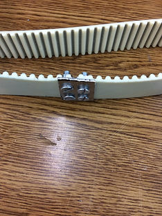
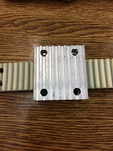
When undertaking the lifting mechanism test, the only belt which was compatible with the pulley drum was fastened together. This meant a full rotation of the motor was not possible and the polarity of the motor had to be swapped whenever the fastener approached the pulley drum. A re-design to the fastener was made which reduced the impact as the belt rotated and was a temporary solution until an appropriately sized belt can be sourced.
After the successful test, the components of the lifting mechanism were assembled in the body of the radio shuttle.